This lab procedure followed the steps outlined in “The Basics of Dielectric Elastomers“ by Soft Machines on YouTube. For a visual and quicker overview of the manufacturing, it would be recommended to follow the video.
Creating the Dielectric Elastomer Layer
Using our polydimethylsiloxane (PDMS) elastomer, Sylgard 184, we created two sample types with differing curing agent ratios. Our first sample used a standard 10:1 ratio, and our modified batch used 20:1. By lowering the curing agent ratio, that batch finished slightly under cured; it was significantly easier to stretch, but also tackier and more delicate than the classic mix.
Each sheet of PDMS was blade-coated onto a sheet of PFA release film at a thickness of 50 microns, and cured at 60° C.
Constructing the DEA
The cured PDMS samples struggled with impurities such as dust, bubble divots, and fingerprints, so only specific sections of our PDMS sheets were used. The desired section was removed from the PFA backing with the use of a custom removal tool, consisting of an acrylic square with double-sided adhesive along each edge. The square was pressed against the PDMS sheet, and used to peel the desired section of PDMS off of the backing.
Once separated from the backing the PDMS inside the square release tool could be freely manipulated. For our flat samples, this meant lightly pre-stretching it to create tension and attaching it down to a smaller acrylic ring.
Now attached to the ring, the carbon grease electrodes were painted on. A small circle was painted in the middle on both sides, taking care to apply the carbon grease as thinly as possible while maintaining a continuous layer. This section where the electrodes on both sides overlap forms the capacitor. It is important to keep the carbon grease as thin as possible here because it will restrict movement when it is later forced to stretch.
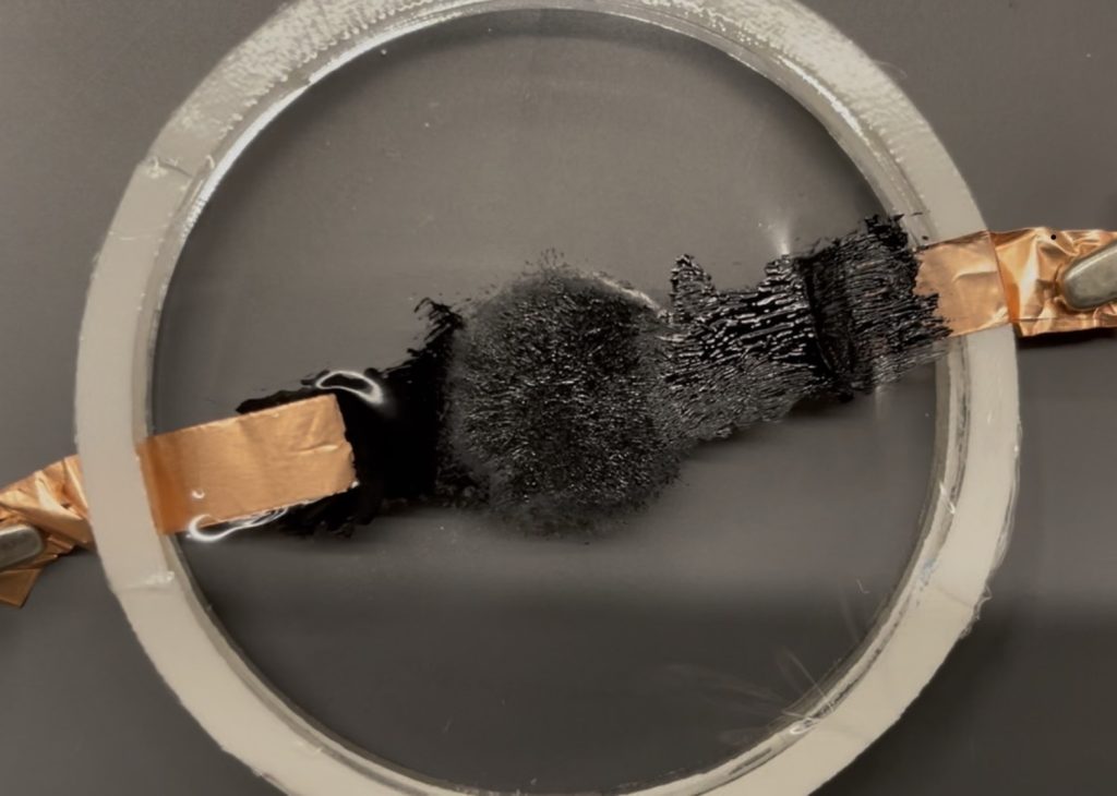
Then, a copper tape lead is attached on each side of the PDMS, coming in from opposite sides of the ring and stoping short of touching central electrode. This gap allows space for the DEA to expand without being limited by the stiff copper tape. To bridge the gap, a thicker layer of carbon grease is painted out from the central electrode to the copper tape, making sure that it has plenty of contact with the copper tape for easy conduction.
Constructing the RDEA
To make the RDEA samples, we first painted on the bottom electrode out of carbon grease, still making sure to keep it as thin as possible, directly onto a PDMS sheet that was still on the backing. The shape of the electrode was a 1 in. x 1 in. square with an additional section off to one side to be a contact point with the copper tape.
We then used a similar technique as with the DEA to separate a second layer of PDMS from its backing. We attached a piece of copper tape to the bottom side. We then laid the second PDMS sheet on top of the first, , such that it could be lined up with the carbon grease contact when the two sheets were brought together. It is important, during this process, to minimize bubbles trapped between the sheets. We then painted a matching electrode square on the top, with a mirrored copper tape contact point. This time we laid the copper tape adhesive side down, but made sure to attach it both above and below the carbon grease contact. This is important because the copper tape does not stick to the grease and must be secured directly to the PDMS.

Finally we cut out the section of PDMS around the electrodes, making sure to leave adequate border, and then rolled up the stacked layers. We started from the bottom, and rolled up towards where the copper tape leads were sticking out of the top, trying to keep the roll as neat and tight as possible.

Testing
Voltage Sweeps
After testing each sample for current leakage at a low voltage, we conducted a DC voltage sweep up to 1 kV in 100 V increments, measuring displacement between the extremes of the DEA samples.
Capacitance
For both flat and rolled samples, we measured capacitance using an LCR meter. This value was then compared to the calculated capacitance from the parallel plates capacitance equation:
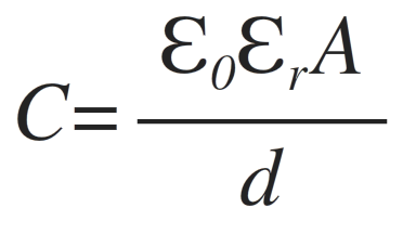
where Eo is vacuum permittivity, Er is permittivity of Sylgard 184 PDMS, A is the area of the PDMS double-coated with carbon grease, and d is the thickness of the PDMS material.
Displacement
Since displacement was minimal and was cut from testing for the RDEA samples, it was adapted to be measured off a custom printed grid. Each grid cell is 0.473mm x 0.473mm, and measurements were rounded up to the nearest hundredth of cell displacement.
Fraction of cell displacement was then multiplied by cell size to get unit measurement of displacement in each direction. To get the total circumferential displacement of our circular area, the resultant displacement was calculated using the equation below:
